ELECTRICITY SYSTEM
PRINCIPLE OF ELECTRICITY
Part of the atom

- Electron- negatively charged particles that revolve around the nuclues of the atom
- Protons- positively charged particles that revolve around the nucleus of the atom
- Neutrons- no charge in the atom
- this parts are important to know because they determine the charge of the atom
- the charge of the atom creates the energy used as electricity
Parts of a Circuit
Consists of 4 parts
- Source
- Conducts
- The Load
- Control Device
1. Source
- Source- Produces the force that causes electrons to move
- Think of a water source that pushes water through a pipe. Same principle
- Electrons(-) are attracted by positive charges, and repelled by negative charges (Oppositr charges attract each other)
2. Conductor or Pat
- Conductor- Provide an easy path for electrons to move throughout the circuit
- Copper is the most commonly used conductor in electronics and residential wiring
- Other conductors include other metals and water
3. Load
- Load- Part of the circuit that changes the energy of the moving electrons into another form of useful energy
- Think of a light bulb as a load
- As electrons move though the filament of the lamp, the energy of electrons in motion is changed into heat and light energy.
4. Control Device
- Control Device-Opens or closes the circuit for electrons to flow.
- A light switch is a great example. The lights are off, electrons can’t flow through to complete the circuit because the switch is open. When the switch is closed, the electrons can flow, and the circuit is closed.
- Switches can be classified as NO (normally open) or NC (Normally closed)
Four Values to Measure Electricity
- Voltage
- Amperage
- Resistance
- Watts
1. Voltage
- The force that moves electrons is call VOLTAGE.
- The unit to measure voltage is known as volts
- The common voltage a residential circuit is 120 volts
- When calculating formulas, voltage is labeled as “E”.
2. Current
- Current – Movement of electrons.
- Current is measured in Amperes or amps.
- A typical residential circuit measures 15 Amps.
- The specifications for a common residential circuit are 120V/15A
- When calculating formulas, current is labeled as “I”.
3. Resistance
- The opposing force in electrical current.
- When electrons flow through a conductor, the are opposed by an insulator. The insulator provides resistance.
- Coating on a wire is the insulator.
- Unit of resistance is the OHM.
- OHM’s law states - Voltage / Current = Resistance
- Power is the time rate of doing work
- Defined in two ways: The rate at which electric energy is delivered to a circuit
- The rate at which an electrical circuit uses electrical energy, or how much work it can do.
Kinds of Circuits
1. Series
- Electrical circuit that only has one path for electrons to flow.
- Open Loop – the circuit is not complete.
- In simple terms, the switch is open, not allowing electrons to flow to the load to complete the circuit.
Voltage Drop
- Voltage Drop- if there are two or more loads in the circuit, the volts are distributed among the loads evenly.
- The total voltage in each load would equal the source.
- Example – Two lights are wired in the same 120V circuit. The voltage in each load will be 60V. Add the two together, =120V.
2. Parallel Circuits
- The loads are connected between the two conductors that lead to the energy source.
- There is no voltage drop if two or more loads are connected in parallel.
- Example – A vanity light that has three lights. If wired in parallel, the voltage at all three loads is 120V, same as the source.
- If wired in series each light bulb would produce only 40 volts each
3. Series Parallel
- Loads operate independently.
- Meaning one switch to a light can be turned off, but another can still operate.
- Example of a parallel circuit – In your kitchen, you might have 3 different lights. Each has their own switch. However, they are connected on the same line, at the breaker box. Hence, there are different lines going to each load from the source
Safety
- Never work in the circuit while it’s plugged in. Always disconnect the lead from the source.
- Before powering up the circuit, make sure all wires are properly connected.
- Never run the circuit with an exposed wire.
INTRODUCTION TO POWER GENERATION
The power generation and energy is back bone of every country to service in this world. Electricity generation is the process of generating electrical power from other source of primary energy. In this chapter power generation are introduced. Concept of the power generation its is about emf (electromotive force). There are six source of electromotive force:-
- pressure
- magnetism
- heat
- light
- chemical
- fraction
The sun's ray can be used to produced a voltage potential using solar cell. Solar system involved the convert of sun's ray to electricity usually using a converter.
Magnetism is a common used for creating an electromotive force by using magnetic. This method used in wind generators, tidal generation , hydro plants( dynamo).
The principle of power generation :
- turbine is spinned powered the dynamo.
- The dynamo consist of wire strands in between magnets.
- wire strands cut through the invisible flux and voltage is produce.
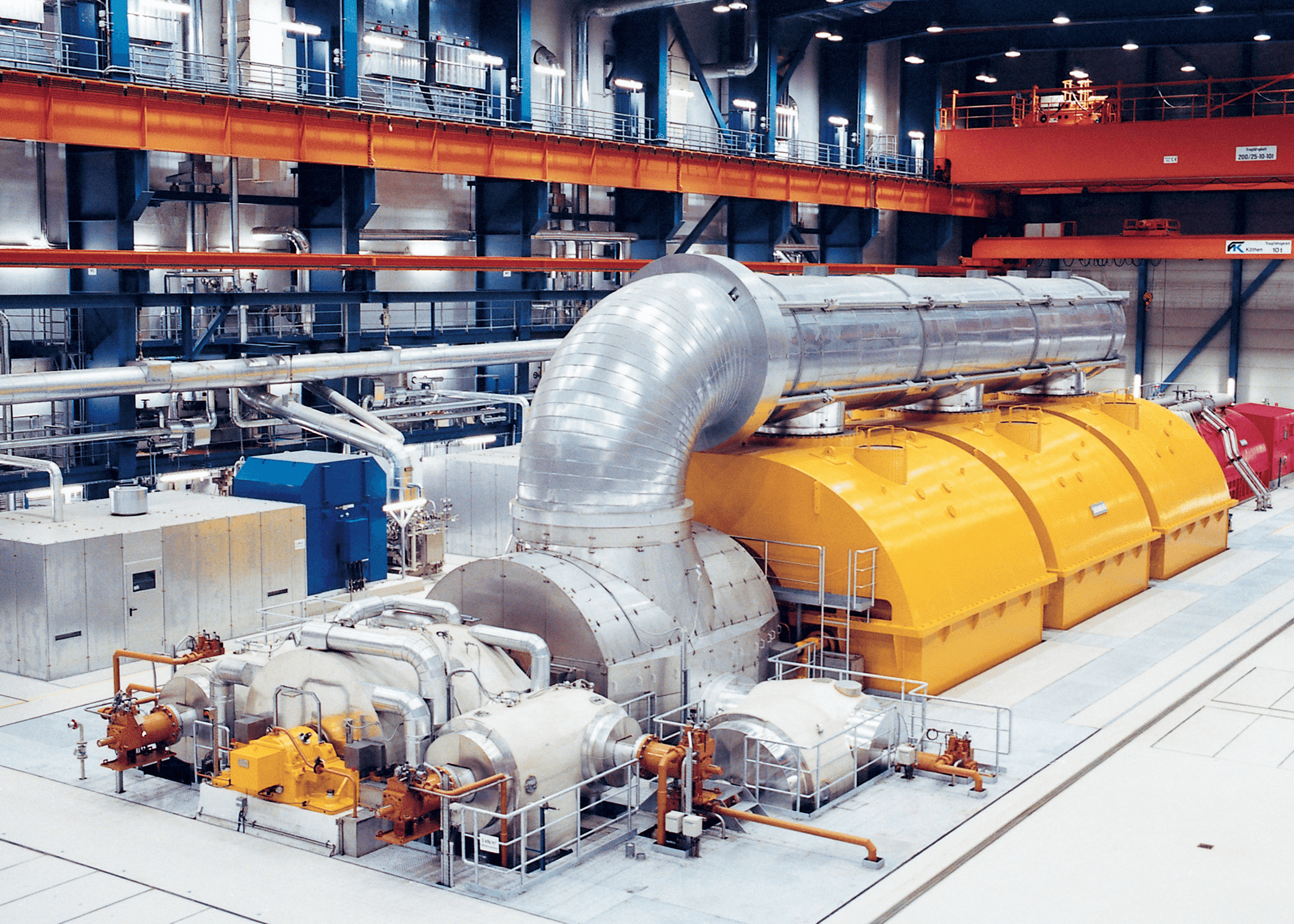 |
| Power generation system via siemens |
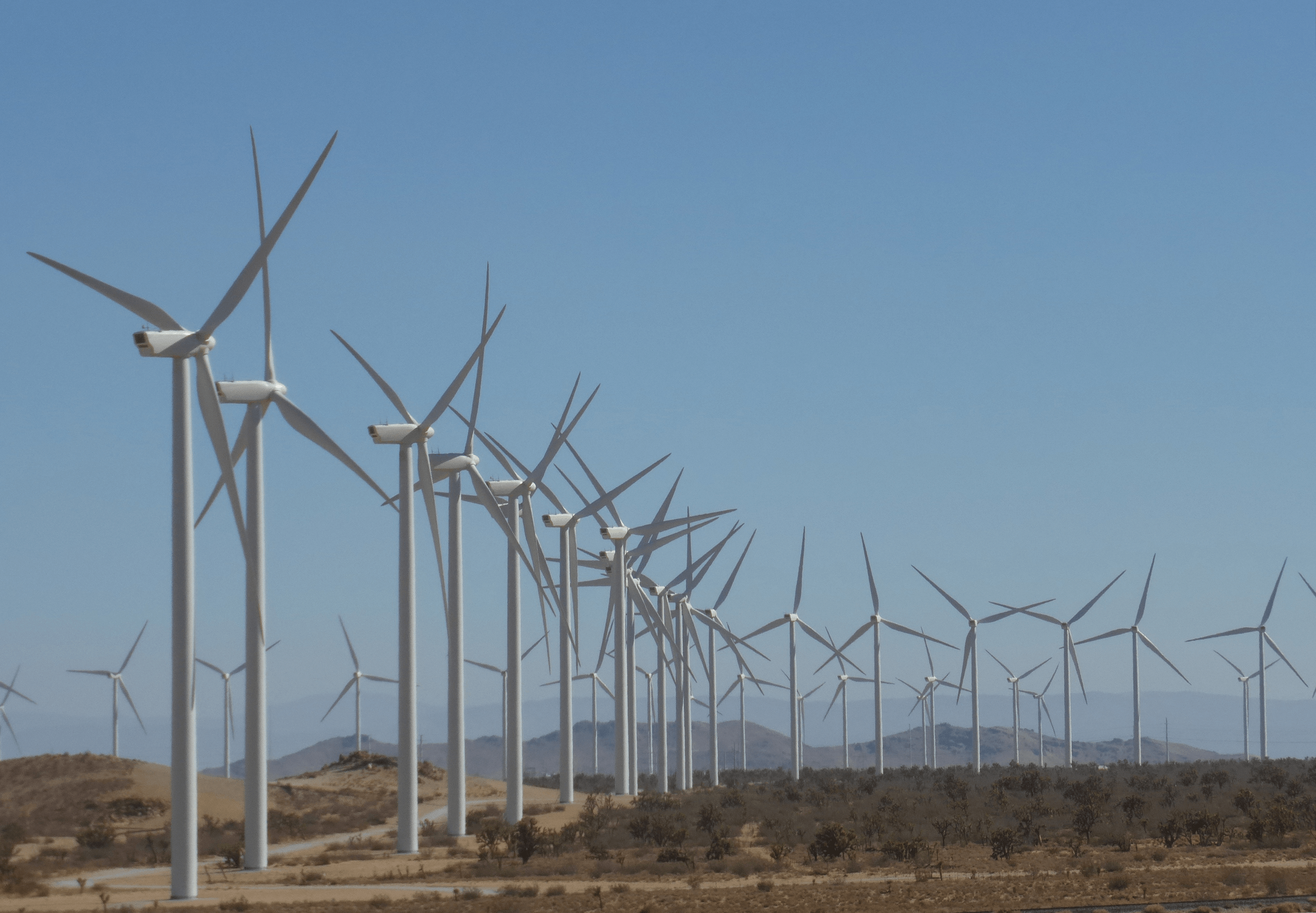 | ||||||||||||||||||||||||||||||||||||||||||||||||||||||
| wind generators Simple calculation of electricity,power,voltage and resistance 
Any two values of
the Voltage, Current or Resistance quantities we can use Ohms Law to find the third
missing value. Ohms Law is
used extensively in electronics formulas and calculations so it is “very
important to understand and accurately remember these formulas”.
To find the Voltage,
( V )
[ V = I x R ] V (volts) = I (amps) x R (Ω)
To find the
Current, ( I )
[ I = V ÷ R ] I (amps) = V (volts) ÷ R (Ω)
To find the
Resistance, ( R )
[ R = V ÷ I ] R (Ω) = V (volts) ÷ I (amps)
It is sometimes
easier to remember this Ohms law relationship by using pictures. Here the three
quantities of V, I and R have been superimposed into a triangle (affectionately called
the Ohms Law Triangle) giving voltage at the top with current and
resistance below. This arrangement represents the actual position of each
quantity within the Ohms law formulas.
Ohms Law Triangle 
Transposing the
standard Ohms Law equation above will give us the following combinations of the
same equation:

For the
circuit shown below find the Voltage (V), the Current (I), the Resistance (R)
and the Power (P).

Voltage [ V = I x R ] = 2 x 12Ω = 24V
Current [ I = V ÷ R ] = 24 ÷ 12Ω = 2A
Resistance [ R = V ÷ I ] = 24 ÷ 2 = 12 Ω
Power [ P = V x I ] = 24 x 2 = 48 W
TYPE
OF CURRENT
Comparison Between Alternating Current And
Direct Current
The type of current using in the case building B11 is direct current
(DC).
OHM’S LAW
Definition:
Ohm's Law states that the current flowing in a circuit is directly
proportional to the applied potential difference and inversely proportional to
the resistance in the circuit.
Ohm’s Law Discovery
MATERIAL IN
ELECTRICAL SYSTEM FOR THE CASE BUILDING
1. Switch
A device that connects and disconnects the flow of electric current in a
circuit. There are many shapes, designs, and types and they are classified as
hanging, flush and surface types.
 
2. Circuit Breaker
A protective device used to automatically blow and cut the current when
trouble in the circuit such as short circuit or overload occur.

3. Junction Box
An octagonal shaped electrical material where the connections or joints
of wires are being done. It is also where the flush type lamp holder is
attached. This coud be made of plastic or metal (PVC) Polyvinyl chloride.

4. Utility Box
A rectangular shaped plastic or metallic (PVC) material in which flush
type convenience outlet and switch are attached.

5. Conduits/Pipes
An electrical materials used as the passage of wires for protection and
insulation. These could be rigid metallic, flexible metallic conduit (FMC),
rigid non-metallic (PVC), and flexible non-metallic or corrugated plastic
conduit (CPC). In this case building, there are more using PVC.

6. Clamps
It is an electrical materials used to hold and anchor electrical
conduits to their proper position.

7. Electrical Wire
Electrical Wire is drawn metal, copper or aluminium that carries
electricity through an electrical circuit. Wire may be run overhead, underground,
through conduit or flex or open. Wire is protected by design with a jacket
depending on usage. It can also be flexible as in the use of extension cords.

COST FOR MATERIAL IN
ELECTRICAL SYSTEM
METHOD OF DISTRIBUTION
1. Sequence Control Circuit
The sequence of control and protective devices contain in the main circuit and consumer final circuit.
A ) Supply Part
lService Fuse and Natural Link
-Protect against excessive current and limiting consumer current

lKWH Meter
-Recording power usage and charge

B ) Consumer Part
l Distribution Board
-It seperates the power supply inti several circuits in an enclosure
-Provides each circuit with its protection system by using a fuse or circuit breaker
-Consist 3 main part ( main switch, residual current breaker, miniture circuit breaker )
3. Final Subcircuits
It is an outgoing circuit connected to a distribution board and intended to supply electrical energy to curent using apparatus, either directly or throught socket-outlets or fused spur-boxes
A ) Lighting Circuit
lA circuit that directly connected to loads and use switch as the control device for light, fans and others
B ) Power Circuit
lA circuit connected to provide electrical energy to portable electrical devices through 13 A and15 A socket
Type of Phase
Single Phase
lSingle phase electricity is generated by rotating a single turn coil through a magnetic field.
lShape of waveform : sine wave
lWire used : Live conductor ( yellow ), Neutral conductor ( blue ), Earth conductor ( green )
lSingle phase electric power means the distribution of alternative current using a system in which all the voltages of the supply vary in unison.
lIt is used when the loads are mostly lighting and heating, with few large electric motors.
lConnected to an alternating current electric motor.
lDoes not produce a revolving magnetic field.
lBenefits:
1. Broad array of application uses
2. Most efficient AC power supply for up to 1000 watts
3. Fewer design costs
4. Less complex designs

Three Phase
lThree phase system generate alternating current which the power flow is constant changing direction.
lThree conductor (lines) to carry the three phase supply, colored red, yellow and blue.
lA fourth conductor called the neutral, connected through protective device to earth.
lThree three phase system is usually connected using star connection ( sources like alternators ) and delta connection ( transformer, motors and other loads ).
lBenefits :
1. Reduction of copper consumption
2. Fewer safety risks for workers
3. Lower labor handling costs
4. Greater conductor efficiency
5. Ability to run higher power loads

Single Phase VS Three Phase
lBoth supplies electricity.
lA single phase supply is smaller than a three phase supply meaning you cannot use a much power.
lA typical domestic users will need a single phase supply whilst a commercial users will need a three phase supply.
lHowever a single phase system may not be the best choice when it comes to industrial or business usage as ti involves heavy load and power requirements.
lSingle phase has one 100 amp fuse and a three phase supply has three 100 amp fuses.
|


No comments:
Post a Comment