Saturday, 21 April 2018

LIGHTING SYSTEM

INTRODUCTION OF LIGHTING 

Lighting controls have traditionally been used to create moods. Today, they are also used as part of a high quality energy efficient lighting system that integrates daylight and electric light sources to provide a comfortable and visually interesting environment for the occupants of a space.

Lighting, at its simplest, consumes energy when electrical current is allowed to pass through restrictive elements of a light fixture. Electrical current passes through an engaged switch, controlled either manually by a physical light switch or electronic remote sensor or automatically via sensor within the space or timer. Lighting designers are concerned with achieving proper lighting levels within the space. The minimum amount of light striking a task surface, or illuminate, is normally designed around Illuminating Engineering Society (IES) requirements, which take into account the types of activities done within the space.Figure 1: Lighting energy consumption is driven by design and usage factors. Courtesy: Arup


LIGHT RESOURCE

Light is an electromagnetic radiation. A particular frequency of this radiation ( around 390-700 nm) is visible to the human eye. Everything that we see around us is because of light. Light is a form of energy and like all energies, it is produced from a source. In physics, these are called Light sources.


TYPES OF LIGHT SOURCES
There are countless sources of light but they can all be categorized under either of the two following categories-
  • Natural sources
  • Artificial sources
       1.      Natural light sources

The universe is filled with objects that emit light. Some of the light from these sources reach the earth. The following things in nature have the ability to emit light:

  • The Sun is the major source of light for the earth. The sun is a massive ball of fire, at the centre of which nuclear fusion produces massive energy. This energy comes out as heat and light. The light from the sun is one of the major factors behind the sustainability of life on earth.
  • Every other star produces light too, but only a small or no amount of it reaches the earth because of the huge distance.
  • The moon provides light as well but it cannot produce light on its own. The light that we get from the moon is the light reflected by it from the sun.
  • Some living organisms have the ability to produce light too. It is called bioluminescence. It is the effect of certain chemical reactions within the organism. Fireflies, jellyfish, glow worm, certain deep sea plants and microorganisms can be cited as examples.

  • Certain other natural phenomena such as lightning and volcanic eruptions also emit light.
  • Natural light controlled by the following factors like number of window, window treatment and placement of rooms

2.      Artificial Light Sources

    Apart from the natural sources, light can be produced artificially too. The different light sources produced artificially can be put under three broad categories-

    a)      Incandescent Sources


    When certain objects are heated to a high temperature,they begin to emit light. Both infrared and visible light is produced in the process.
    Thomas Alva Edison invented the first electric light bulbs in 1879AD.
    Contains nitrogen or argon gas 
    Tungsten filament with lead wires – burns when electricity is passed
    Advantage is light quality and colour are very consistent.
    Disadvantage is requires lot of energy and faster degradation of filament leading to shorter lifespan.
    Example- Candle, incandescent lamp.


    b) Fluorescent light


    Contains argon/krpton as gas vapour with phosper coating on the walls of glass tube.
    Electricity released through a mercury vapour in a tube 
    Advantage is low production cost and long life of tubes.
    Disadvantage is poorly designed ballasts can create fires when they overheat
    Example- Fluorescent tube light


    c) Gas Discharge Sources:
    Passing electricity through certain gases at a very low pressure can produce light too.
    Provide high luminous efficacy combined with long life, resulting in the most economical light source available.
    Example – Neon lamp, Sodium lamp.

       For the case building B11 in Utm, there are using two type of light resource which are natural and artificial. Learning spaces like classroom and studios use types Fluorescent lamps rather than incandescent bulbs. In this case building, fluorescent tube light is using in classroom, toilet, hallway and etc.
    Fluorescent tube light in classroom

    Fluorescent tube light at hallway
    Fluorescent tube light in toilet
       Types of bulb

    1.            1.   Incandescent bulb
       -most common light used in homes
       -most commonly used light bulb and usually the least expensive.
       -light has warm,inviting quality and very complimentary.
        In our case building B11, this bulb is not use now.


          2.   Halogen bulb
                 -variation of incandescent
                 -a little more energy efficient but are more expensive and burn higher temperature.
                 -used at cabinet lighting, pendant lights and recessed cans.
                 In our case building this bulb cannot be used.


          3.   Fluorescent bulb
                -gives a flat, cold light, often bluish and harsh.
                -produce more light and last longer than incandescent.
                In our case building this bulb is most used in every places in building.  


         4.   LED lamp light
    -more energy-efficient than CFL bulbs.
    -CFLs will have more trouble qualifying for the Energy Star rating.
    -The cost has been decreasing in recent years.
    In building B11 this bulb cannot be used because of many reasons.


     5.   Compact fluorescent lamp
             -designed to replace an incandescent light bulb. 
              In building B11, this bulb usually used for certain room lecturer.  


          6.   Arc lamp
    - produce light by an arc between metal electrodes through an inert gas in a glass bulb. 
    In our case study, bulb type this cannot be used.


          7.   Metal-halide lamp
               -  electrical lamp that produces light.
               - most common metal halide compound used is sodium iodide. In our case study, bulb type this are not used.


    ABOUT LED LAMP OR BULB

    A LED lamp or LED light bulb is an  electric light for use in light fixture that produces light using Light- Emmiting Diode(LED). LED lamps have a lifespan and electrical efficiency which are several times greater than incandescent lamps, and are significantly more efficient than most fluorescent lamps,with some chips able to emit more than 300 lumens per watt.

    1. Life time of LED Lighting Products
    • The useful life of LED lighting products is defined differently than that of other light sources, such as incandescent or compact fluorescent lighting (CFL). LEDs typically do not “burn out” or fail.
    • Instead, they experience ‘lumen depreciation’, wherein the brightness of the LED dims slowly over time. 
    • Unlike incandescent bulbs, LED “lifetime” is established on a prediction of when the light output decreases by 30 percent.
    2. LEDs and Heat

    • LEDs use heat sinks to absorb the heat produced by the LED and dissipate it into the surrounding environment. This keeps LEDs from overheating and burning out.
    • Thermal management is generally the single most important factor in the successful performance of an LED over its lifetime. The higher the temperature at which the LEDs are operated, the more quickly the light will degrade, and the shorter the useful life will be.
    • LED products use a variety of unique heat sink designs and configurations to manage heat.
    • Today, advancements in materials have allowed manufacturers to design LED bulbs that match the shapes and sizes of traditional incandescent bulbs.
    • Regardless of the heat sink design, all LED products that have earned the ENERGY STAR have been tested to ensure that they properly manage the heat so that the light output is properly maintained through the end of its rated life.
    ENERGY STAR means high quality and performance, particularly in the following areas:

    Color Quality

       o 5 different requirements for color to ensure quality up front and over time.

    Light Output

       o Light output minimums to ensure you get enough light.
       o Light distribution requirements to ensure the light goes where you need it.
       o Guidelines for equivalency claims to take the guess-work out of replacement.

    Peace of mind

       o Verified compliance with more than 20 requirements to address performance and labeling.
       o Long-term testing to back up lifetime claims.
       o 3-year minimum warranty requirement.

    Schematic symbol of lighting system

    Electronic symbol is a pictogram used to represent various electrical and electronic devices or functions such as wires, batteries, resistors and transistors in a schematic diagram of an electrical or electronic circuit.


    ELECTRICITY SYSTEM 

    PRINCIPLE OF ELECTRICITY

    Part of the atom
    相关图片

    • Electron- negatively charged particles that revolve around the nuclues of the atom
    • Protons- positively charged particles that revolve around the nucleus of the atom
    • Neutrons- no charge in the atom
      • this parts are important to know because they determine the charge of the atom
      • the charge of the atom creates the energy used as electricity

    Parts of a Circuit
    Consists of 4 parts
    • Source
    • Conducts
    • The Load
    • Control Device
    1. Source
    •  Source- Produces the force that causes electrons to move
    • Think of a water source that pushes water through a pipe. Same principle
    • Electrons(-) are attracted by positive charges, and repelled by negative charges (Oppositr charges attract each other)

    2. Conductor or Pat

    •  Conductor- Provide an easy path for electrons to move throughout the circuit 
    • Copper is the most commonly used conductor in electronics and residential wiring
    • Other conductors include other metals and water
     3. Load
    • Load- Part of the circuit that changes the energy of the moving electrons into another form of useful energy
    •  Think of a light bulb as a load
    • As electrons move though the filament of the lamp, the energy of electrons in motion is changed into heat and light energy.
     4. Control Device
    • Control Device-Opens or closes the circuit for electrons to flow.
    • A light switch is a great example. The  lights are off, electrons can’t flow through to complete the circuit because the switch is open. When the switch is closed, the electrons can flow, and the circuit is closed.
    •  Switches can be classified as NO (normally open) or NC (Normally closed)

     Four Values to Measure Electricity

    • Voltage
    • Amperage
    • Resistance
    • Watts 
     1. Voltage
    • The force that moves electrons is call VOLTAGE.
    •  The unit to measure voltage is known as volts
    •  The common voltage a residential circuit is 120 volts
    • When calculating formulas, voltage is labeled as “E”.
     2. Current
    •  Current – Movement of electrons.
    •  Current is measured in Amperes or amps.
    •  A typical residential circuit measures 15 Amps.
    •  The specifications for a common residential circuit are 120V/15A
    •  When calculating formulas, current is labeled as “I”.
     3. Resistance
    • The opposing force in electrical current.
    • When electrons flow through a conductor, the are opposed by an insulator. The insulator provides resistance.
    •  Coating on a wire is the insulator.
    •  Unit of resistance is the OHM.
    •  OHM’s law states - Voltage / Current = Resistance
    4. Power and Watt Law
    • Power is the time rate of doing work
    •  Defined in two ways: The rate at which electric energy is delivered to a circuit
    •  The rate at which an electrical circuit uses electrical energy, or how much work it can do.

     Kinds of Circuits

    1. Series 
    • Electrical circuit that only has one path for electrons to flow.
    • Open Loop – the circuit is not complete. 
    • In simple terms, the switch is open, not allowing electrons to flow to the load to complete the circuit.
     Voltage Drop
    • Voltage Drop- if there are two or more loads in the circuit, the volts are distributed among the loads evenly.
    • The total voltage in each load would equal the source.
    • Example – Two lights are wired in the same 120V circuit. The voltage in each load will be 60V. Add the two together, =120V. 
     2. Parallel Circuits
    • The loads are connected between the two conductors that lead to the energy source.
    • There is no voltage drop if two or more loads are connected in parallel.
    • Example – A vanity light that has three lights. If wired in parallel, the voltage at all three loads is 120V, same as the source.
    •  If wired in series each light bulb would produce only 40 volts each
     3.  Series Parallel
    • Loads operate independently.
    • Meaning one switch to a light can be turned off, but another can still operate.
    • Example of a parallel circuit – In your kitchen, you might have 3 different lights. Each has their own switch. However, they are connected on the same line, at the breaker box. Hence, there are different lines going to each load from the source
     Safety
    • Never work in the circuit while it’s plugged in. Always disconnect the lead from the source.
    • Before powering up the circuit, make sure all wires are properly connected. 
    •  Never run the circuit with an exposed wire.


    INTRODUCTION TO POWER GENERATION

    The power generation and energy is back bone of every country to service in this world. Electricity generation is the process of generating electrical power from other source of primary energy. In this chapter power generation are introduced. Concept of the power generation its is about emf (electromotive force). There are six source of electromotive force:-
    • pressure
    • magnetism 
    • heat
    • light
    • chemical
    • fraction
    A battery uses a chemical effect to produce electromotive force. the chemical effect is achieved by placing two dissimilar metals into an electrolyte. An example is the placement of copper and zinc electrode together in the solution of sulphuric acid. The chemical energy turn to electric energy.

    The sun's ray can be used to produced a voltage potential using solar cell. Solar system involved the convert of sun's ray to electricity usually using a converter.

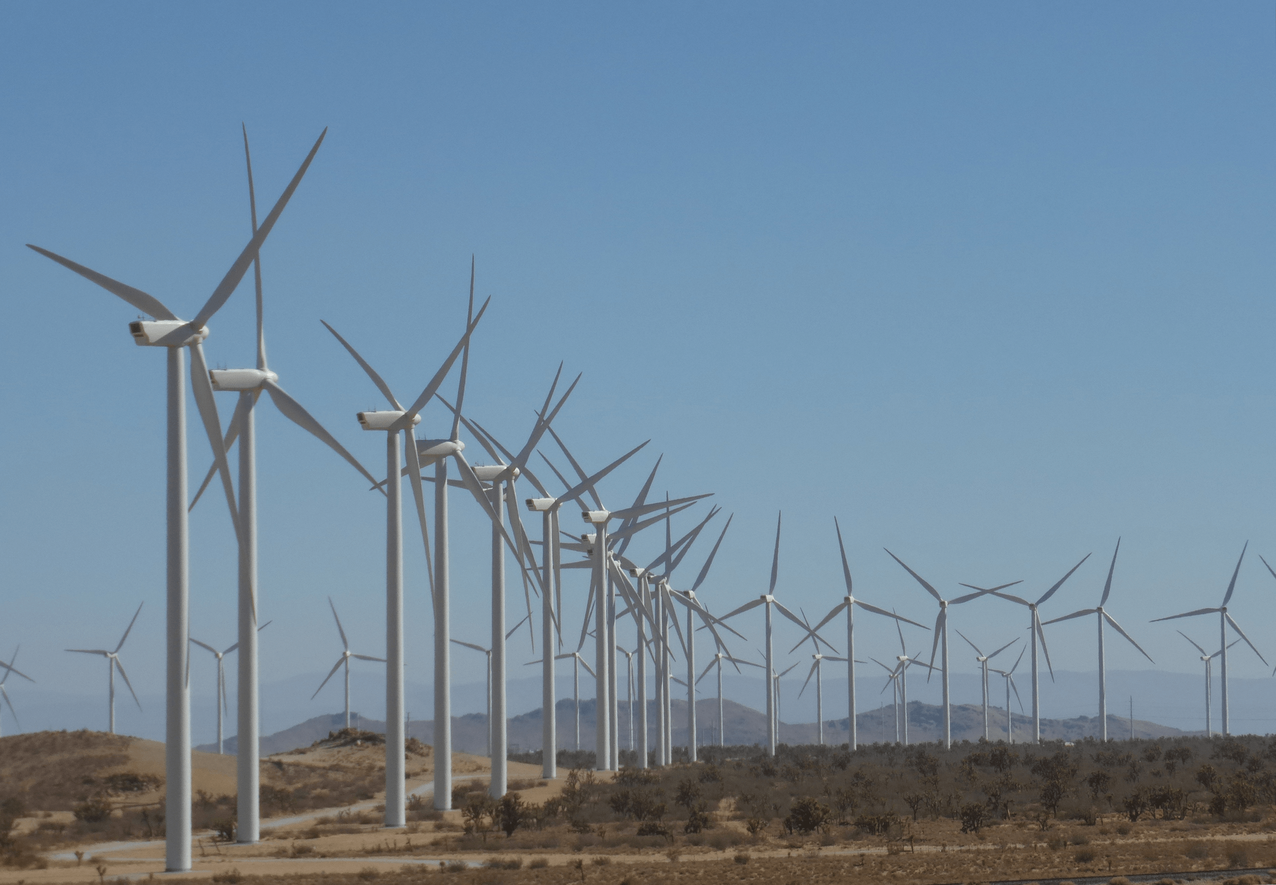
    Magnetism is a common used for creating an electromotive force by using magnetic. This method used in wind generators, tidal generation , hydro plants( dynamo).

    The principle of power generation :
    1. turbine is spinned powered the dynamo.
    2. The dynamo consist of wire strands in between magnets.
    3. wire strands cut through the invisible flux and voltage is produce.

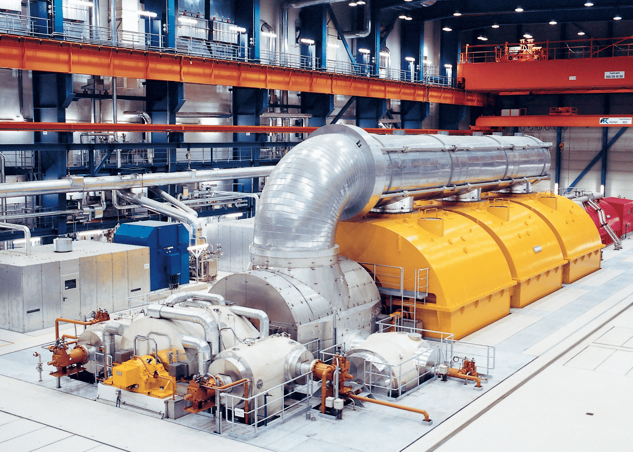
    Power generation ssytem
    Power generation system via siemens
    Wind energy
    wind generators


    Simple calculation of electricity,power,voltage and resistance


    ohms law


    Any two values of the Voltage, Current or Resistance quantities we can use Ohms Law to find the third missing value. Ohms Law is used extensively in electronics formulas and calculations so it is “very important to understand and accurately remember these formulas”.
    To find the Voltage, ( V )
    [ V = I x R ]      V (volts) = I (amps) x R (Ω)
    To find the Current, ( I )
    [ I = V ÷ R ]      I (amps) = V (volts) ÷ R (Ω)
    To find the Resistance, ( R )
    [ R = V ÷ I ]      R (Ω) = V (volts) ÷ I (amps)


    It is sometimes easier to remember this Ohms law relationship by using pictures. Here the three quantities of VI and R have been superimposed into a triangle (affectionately called the Ohms Law Triangle) giving voltage at the top with current and resistance below. This arrangement represents the actual position of each quantity within the Ohms law formulas.


    Ohms Law Triangle


    ohms law triangle


    Transposing the standard Ohms Law equation above will give us the following combinations of the same equation:


    ohms law triangle relationship


    For the circuit shown below find the Voltage (V), the Current (I), the Resistance (R) and the Power (P).
    ohms law circuit
    Voltage   [ V = I x R ] = 2 x 12Ω = 24V
    Current   [ I = V ÷ R ] = 24 ÷ 12Ω = 2A
    Resistance   [ R = V ÷ I ] = 24 ÷ 2 = 12 Ω
    Power   [ P = V x I ] = 24 x 2 = 48 W

    TYPE OF CURRENT

    • Electric current comes in two varieties: alternating current and direct current, abbreviated as AC and DC. Both types have their own specific uses in terms of power generation and use, although AC is the more common type of electrical current in the home.
    • If electrons always flows in one direction, the electric current is called direct current (d.c.). An electric caused by a chemical cell or a battery is a direct current.
    • If an electric current in a circuit reverses direction every so often, it is called an alternating current (a.c.). For example, the current that flows through a domestic light bulb when connected to the mains electricity supply reverses direction 100 times every second and is therefore an alternating current.
    Comparison Between Alternating Current And Direct Current


    Alternating Current
    Direct Current
    Amount of energy that can be carried
    Safe to transfer over longer city distances and can provide more power.
    Voltage of DC cannot travel very far until it begins to lose energy.
    Cause of the direction of flow of electrons
    Rotating magnet along the wire
    Steady magnetism along the wire.
    Frequency
    The frequency of alternating current is 50Hz or 60Hz depending upon the country.
    The frequency of direct current is zero.
    Direction
    It reverses its direction while flowing in a circuit.
    It flows in one direction in the circuit.
    Current
    It is the current of magnitude varying with time
    It is the current of constant magnitude.
    Flow of electrons
    Electrons keep switching directions - forward and backward.
    Electrons move steadily in one direction or 'forward'.
    Obtained from
    A.C Generator and mains.
    Cell or Battery
    Passive Parameters
    Impedance.
    Resistance only
    Power Factor
    Lies between 0 & 1.
    It is always 1.
    Types
    Sinusoidal, Trapezoidal, Triangular, Square.
    Pure and pulsating

    The type of current using in the case building B11 is direct current (DC).

    OHM’S LAW

    Definition:
    Ohm's Law states that the current flowing in a circuit is directly proportional to the applied potential difference and inversely proportional to the resistance in the circuit.
    • In other words by doubling the voltage across a circuit the current will also double. However if the resistance is doubled the current will fall by half.
    • Ohm's Law is one of the most fundamental and important laws governing electrical and electronic circuits.
    • Ohm's Law relates the voltage or potential across a load to the current flowing through it.
    Ohm’s Law Discovery
    • There is a mathematical relationship which links current, voltage and resistance.
    • A German scientist named George Ohm performed many experiments in an effort to show a link between the three.
    • In the days when he was performing his experiments there were no meters as we know them today.
    • Only after considerable effort and at the second attempt did he manage to devise what we know today as Ohm's Law.
    MATERIAL IN ELECTRICAL SYSTEM FOR THE CASE BUILDING

    1.  Switch

    A device that connects and disconnects the flow of electric current in a circuit. There are many shapes, designs, and types and they are classified as hanging, flush and surface types.


    2. Circuit Breaker

    A protective device used to automatically blow and cut the current when trouble in the circuit such as short circuit or overload occur.


    3. Junction Box

    An octagonal shaped electrical material where the connections or joints of wires are being done. It is also where the flush type lamp holder is attached. This coud be made of plastic or metal (PVC) Polyvinyl chloride.


    4. Utility Box

    A rectangular shaped plastic or metallic (PVC) material in which flush type convenience outlet and switch are attached.


    5. Conduits/Pipes

    An electrical materials used as the passage of wires for protection and insulation. These could be rigid metallic, flexible metallic conduit (FMC), rigid non-metallic (PVC), and flexible non-metallic or corrugated plastic conduit (CPC). In this case building, there are more using PVC.


    6. Clamps

    It is an electrical materials used to hold and anchor electrical conduits to their proper position.


    7. Electrical Wire

    Electrical Wire is drawn metal, copper or aluminium that carries electricity through an electrical circuit. Wire may be run overhead, underground, through conduit or flex or open. Wire is protected by design with a jacket depending on usage. It can also be flexible as in the use of extension cords.


    COST FOR MATERIAL IN ELECTRICAL SYSTEM

    Material in electrical
    Unit
    Price(RM)
    Switch
    1 unit
    7.00
    Circuit Breaker
    1 unit
    20.00
    Junction Box
    1 unit
    3.00
    Conduits / Pipes
    1 meter
    3.80
    Clamp
    1 unit
    0.30
    Electrical wire
    1 meter
    3.50


    METHOD OF DISTRIBUTION


    1. Sequence Control Circuit
    The sequence of control and protective devices contain in the main circuit and consumer final circuit.

    A ) Supply Part
    lService Fuse and Natural Link
    -Protect against excessive current and limiting consumer current


    lKWH Meter
    -Recording power usage and charge


    B ) Consumer Part
    l Distribution Board
    -It seperates the power supply inti several circuits in an enclosure
    -Provides each circuit with its protection system by using a fuse or circuit breaker
    -Consist 3 main part ( main switch, residual current breaker, miniture circuit breaker )


    3. Final Subcircuits
    It is an outgoing circuit connected to a distribution board and intended to supply electrical energy to curent using apparatus, either directly or throught socket-outlets or fused spur-boxes
    A ) Lighting Circuit
    lA circuit that directly connected to loads and use switch as the control device for light, fans and others

    B ) Power Circuit
    lA circuit connected to provide electrical energy to portable electrical devices through 13 A and15 A socket

    Type of Phase


    Single Phase
    lSingle phase electricity is generated by rotating a single turn coil through a magnetic field.
    lShape of waveform : sine wave
    lWire used : Live conductor ( yellow ), Neutral conductor ( blue ), Earth conductor ( green )
    lSingle phase electric power means the distribution of alternative current using a system in which all the voltages of the supply vary in unison.
    lIt is used when the loads are mostly lighting and heating, with few large electric motors.
    lConnected to an alternating current electric motor.
    lDoes not produce a revolving magnetic field.
    lBenefits:
    1. Broad array of application uses
    2. Most efficient AC power supply for up to 1000 watts
    3. Fewer design costs
    4. Less complex designs


     Three Phase
    lThree phase system generate alternating current which the power flow is constant changing direction.
    lThree conductor (lines) to carry the three phase supply, colored red, yellow and blue.
    lA fourth conductor called the neutral, connected through protective device to earth.
    lThree three phase system is usually connected using star connection ( sources like alternators ) and delta connection ( transformer, motors and other loads ).
    lBenefits :

    1. Reduction of copper consumption
    2. Fewer safety risks for workers
    3. Lower labor handling costs
    4. Greater conductor efficiency
    5. Ability to run higher power loads


    Single Phase VS Three Phase
    lBoth supplies electricity.
    lA single phase supply is smaller than a three phase supply meaning you cannot use a much power.
    lA typical domestic users will need a single phase supply whilst a commercial users will need a three phase supply.
    lHowever a single phase system may not be the best choice when it comes to industrial or business usage as ti involves heavy load and power requirements.
    lSingle phase has one 100 amp fuse and a three phase supply has three 100 amp fuses.


    solar system

    Solar Energy Introduction Usage Projection       The problem what the world is facing nowadays  is  the  energy  prob...